T.E.(Terry) Manning
Schoener 50
1771 ED Wieringerwerf
The Netherlands
Tel/fax 0031-227-604128
Homepage: http://www.flowman.nl
E-mail:pumps@flowman.nl
FLOWMAN
ADVANCED PUMP TECHNOLOGIES
Edition 08: 22 December,2002
SOLAR SPRING SOLAR PUMPS
INSTALLATION
The following pages are about checking the installation and water flow. If you are more interested in other aspects concerning installation, please return to
INSTALLATION INDEX
CHECKING INSTALLATION
CHECK LIST:
| PHYSICAL | 1) Solidity of panel support structure |
| SAFETY | 1) Safety rope fastened |
| 2) Sealing off of bore-hole |
| ELECTRICAL | 1) Voltages of controller and motor matching |
| 2) Electric cable to controller connections |
| 3) Controller to panel connections |
| 4) Panel to panel connections |
| ORIENTATION | 1) Panels pointing south (North H.) or north (South H.) |
| 2) Freedom from obstructions |
| 3) Array correctly tilted |
| HYDRAULICS | 1)Water in bore-hole ? What level ? Installation depth OK? |
| 2) Feed pipe without kinks |
| 3) Feed pipe correctly embedded |
| 4) Water tank or other recipient connected |
| 5) In some cases the valves may stick after storage.See notes below. |
USE OF CONTROLLER DIAGNOSTICS
When the pump is connected directly (therefore without batteries) to the solar panels, operations under way and the status of the system can be checked by looking at the four LED lights which can be seen when the lid of the controller box is removed.
Do not touch any metallic or non metallic part inside the controller.
These four LED lights enable an initial rapid check of operation to be made on first installation or on re-installation after maintenance.
Only a few things can in practice happen with a pump running directly from PV panels through a Sunprimer controller. To carry out a full diagnosis, at least two commercial testers (= 2 voltmeters and 2 ampmeters) are needed as well as the LED lights.
When all four LED lights are off then EITHER the controller is not connected to the panels OR the safety devices having discovered damage to the main transistor such as to prevent normal operation of the controller, have put the PV panels into short circuit.
THE LED LIGHTS ARE NUMBERED ACCORDING TO CIRCUIT LOGIC.
The first LED, the third from the top, (shown in the drawing as no. 1) lights up when a voltage greater than about 10V reaches the controller from the panels.
The second LED, the second from the top, (shown on the drawing as no. 2) lights up when the main capacitor is charging. This phase lasts about three minutes with the Mk I/d and Mk I/e controllers and about 2 minutes with the Mk II controller. Note that in certain circumstances the capacitor may be impeded by built in safety mechanisms from charging.
The third LED, the one at the bottom, (shown on the drawing as no. 3) lights up when the controller sends output voltage greater than about 10V to the pump motor.
The fourth LED, the one at the top, (shown on the drawing as no. 4) lights up when the pump motor stops because the external (float) switch is in OFF mode.
CHECKING LED DIAGNOSTICS
No LED lights come on
If no LED lights come on, then either the connections between the panels or the battery set and the controller are such that no current arrives to the controller, or that the built in safety devices having sensed damage to the main transistor have put the panels or the battery set into short circuit. In case of the battery set, the fuse should have burned out. First check the electrical contacts. Then remove the electrical supply to the controller, where appropriate (battery installations) substitute the burned out fuse, and reconnect the power supply to see if the fault is still there. Should operation become normal then there was a temporary system block due to a false alarm caused by accidental voltage surges which were not self-correcting. If the defect is still there, the diagnosis should be completed by placing an ampmeter and a voltmeter between the panels or the battery set and the controller. If voltage is too low and no current passes, then there is a fault with the electrical connection or with the PV panels. If current passes normally from the panels but there is no voltage (or just a few volts) then either the battery fuse continues to jump or the PV panels or the battery set are in short circuit mode and there is a defect in the controller.
Only the first LED (the third from the top) lights up
If just the first LED, the third from the top marked on the drawing as no. 1 comes on but not the second LED (the second from the top marked on the drawing as no. 2), or if both the first (the third from the top marked on the drawing as no. 1) and the second LED (the second from the top marked on the drawing as no. 2) light up regularly but after at least three minutes (Mk I/d and Mk I/e) or two minutes (Mk II) not the third LED (the third bottom LED marked on the drawing as no. 3), then the voltage of the main capacitor is insufficient for the system to work normally. This can be due to:
a)Insufficient insolation
b)PV panels are not suitable
c)Faulty electrical input connections
d)(In case of the Mk I/d controller only) wrong position of the two/four panel switch in the controller circuit (in the two panel mode the capacitor will reach a voltage of about 30V, in four panel mode about 57V). The capacitor voltages are such that they can be reached by any correctly wired commercially available PV panels even in the worst temperature conditions.
e)Battery set is discharged
f)Break in the electric cable going to the pump
g)Brush wear
h)Controller break down
To check whether the the capacitor voltage is in order without the need to open or access the internal part of the controller box, connect a voltmeter to the ends of the two float switch wires. Since these wires are connected to the capacitor through resistors for short circuit protection purposes, they can be safely used to check capacitor voltage.
To check for brush wear and eventual break in the electric cable, use a "tester" to check the global circuit resistance. If this is about 10000 Ohm, the brushes are worn out. If it is nearly infinity, then there is a break in the cable.
To check the other factors, without removing the first voltmeter, add a second voltmeter to the panel circuit and an ampmeter on the pump motor circuit.
a)Where four panels are installed, each pair of panels has to be checked either contemporaneously or one after the other. If panel voltage is normal but there is no current or a current of just a few milliamperes and the capacitor voltage does not go up, then the main capacitor charging and discharging thyristor is broken. If there is a current of several amperes then an attempt should be made to stop the controller by putting the two float switch wires in contact with one another BY MEANS OF A GOOD QUALITY FAST SNAP SWITCH (NEVER NEVER USE YOUR HANDS FOR THIS OPERATION!!). If current in the pump motor circuit fails to switch off then the main controller transistor has burned out and at the same time the resistance of the cable between the controller and the pump motor is too high (see "Cable resistance" below). If the current switches off then the main controller transistor is in order and the cable between the controller and the pump motor offers too much resistance (i.e. it is too small). Should capacitor voltage rise, check the voltage level reached.
b)Where two panels are installed, if voltage does not exceed 30V then there is something wrong with the panels. If voltage is more than 30V and the system does not start, then where a Mk I/d or a Mk I/e controller is being used, make sure the switch inside the controller box is in two panel mode. If the system still does not start there is a fault in the controller.
c)Where four panels are installed, if voltage does not exceed 60V then either there is something wrong with the panels or there is a fault in the automatic series/parallel switching mechanism of the controller with the result that the panels remain in parallel instead of switching to series. This can be confirmed by measuring the maximum voltage reached by the capacitor and contemporaneously the voltage reached by each pair of panels to see whether the maximum voltage of the capacitor is the sum of the voltages given by the two pairs of panels or whether it is equal to the voltage of just one pair of panels.
First and second LEDs light up
If the first LED (the third from the top marked on the drawing as no. 1) and the second LED (the second from the top marked on the drawing as no. 2) light up regularly and after about three minutes (Mk I/d and Mk I/e controlelrs) or 2 minutes (Mk II controller) the third LED (the bottom LED top marked on the drawing as no. 3) comes on and then goes out then the pump has not managed to start, or started but switched off immediately. This can happen repeatedly on a cyclical basis because:
a)Insolation is too low
b)The PV array is too small for the application in question
c)The pump is too deeply submerged under water
d)The resistance of the cable between the controller and the pump is too high (= the cable is too small)
e)The load is too high for the pump to handle and/or the cam size used is too large.
f)The internal (MK I/d) controller switch is in two panel mode when it should be in four panel mode.
g)Built in safety devices have acted to cut current where current has reached a value of 4.5 amps for half a second due to blockage of the feed pipe through freezing or other causes.
h)Very rarely, failure to start due to reduction of current surge caused by obstruction of the small self-cleaning nipple of the residual pressure release device situated at the lower end of the feed pipe. Should this occur, just wobble the wiggle wire potruding from the nipple.
i)It can also happen that a four panel system fail to start because the two pairs of panels are not equal or insolation on them is not equal.
First second and third LEDs light up
If the first (the third from the top marked on the drawing as no. 1), second (the second from the top marked on the drawing as no. 2) and third LED (s light up properly and operation appears normal but no water is pumped, then an ampmeter should be inserted in the pump motor circuit. If current equal to or less than that shown on the tables is produced when the third LED lights up, and there is no water, then either the pump is out of the water (= running dry) or it cannot self-prime, in which case refer to the further notes on priming in this section of the instructions. If, instead, the third LED lights up but no current passes, then either the electric cable is cut or the motor brushes require replacement. This can be counter-tested for a 10000 Ohm resistance as set out above.
All LEDs appear to behave regularly
If everything operates as expected and the pump starts normally after initial connection to the panels or with the early morning sun but then after the passage of a cloud or for some other reason fails to start up again, then either:
a)The main thyristor of the capacitor charging device has broken down
b)Resistance between the pump motor and the controller is too high (cable is too small)
c)Excessive cable resistance coupled with damage to the main controller transistor.
In such case, insert a voltmeter between the float switch wires (use a good switch for the purpose NOT your hands!!) and an ampmeter in the pump motor circuit and then try to recreate the situation which led to the malfunctioning, e.g. by turning the panels out of the sun or shadowing them to simulate the passage of a cloud causing a reduction in insolation requiring the intervention of the controller.
If, in case of failure to re-start, voltage is normal but there is either no current or current is just a few milliamperes, and capacitor voltage does not go up, then the main capacitor charging and discharging thyristor is defective (=the thyristor manufacturer has failed to respect his stated manufacturing tolerances) and the thyristor may need replacement.
If current to the order of a few amps passes then try to turn the controller off by putting the two float switch wires in contact (use a good quality switch for this purpose, NOT your hands!!). If current in the pump motor circuit is not switched off then the main controller transistor has burnt out AND ALSO the cable resistance is too high (= the cable is too small)(see "Cable resistance" below). If the current switches off, then the problem is just the resistance and size of the electric cable between the pump and the controller.
If capacitor voltage goes up, then refer back to "Only the first LED lights up" above.
CABLE RESISTANCE
The overall resistance of the cable between the controller and the pump must be less than 1.5 Ohm. Purely indicatively this in normal conditions will correspond to cables with a section of 2.5mm2 for lengths up to 80m, 4mm2 for lengths up to 150m, and 6mm2 for cables longer than 150m, assuming at all times that the wires are pure copper and cable joints are few and well executed. Since the resistance of the motor windings is about 1.4 Ohm, the global resistance of the pump motor circuit measured at the tips of the wires leaving the controller should be less than 2.9 Ohm. This resistance must be measured very carefully as some commercial testers are too inaccurate at lower resistances while others using very low test currents may be disturbed by weak electical forces caused by interference amongst various materials present in the circuit to be measured.
The resistance of the cable between the controller and the pump must be low because the controller governs the outlet voltage towards the pump motor and if the voltage falls below 20V it cuts current supply to the pump as it feels the pump is about to stop. If the cable resistance is too high, voltage could because of ohmic effects (V=RxI) remain over 20V even where the pump has stopped, with the result that the controller cannot do its work and cut current supply to the motor. Were this to occur for instance after the passage of a cloud, the system would correct itself only once current has been cut either autonomously at nightfall or through the operation of built in safety systems where current reaches 4.5 amps for half a second or through the operation of the float switch or other external control.
REDUCED CAPACITY
If after a period of normal operation at parity of insolation during the middle of the day the pump produces less water than expected, the cause can be:
a)Badly connected panels cables
b)Incorrect seasonal or latitudinal panel orientation
c)Undersizing of PV panel array
d)Incorrect cam size (cam size TOO LARGE) with the result that the pumps stays in parallel mode instead of passing into series mode.
First check the electrical connections.
Then insert a voltmeter in the pump circuit.
If a pump unit with a four panel system starts later in the morning and stops earlier in the evening, then the series/parallel switching device of the controller could be damaged or electrical connections could be faulty. Use a voltmeter in the pump circuit to check electrical connections. Voltage during normal high insolation operation will typically be 50-60V. Where insolation is weaker, voltage is halved to about 30V to ensure operation for instance in the morning or in the evening or in cloudy weather. If insolation becomes very weak, then the pump switches off. If, after having put a voltmeter in the pump motor circuit, there is no evidence of operation at the lower voltage in the morning or in the evening or when passing clouds are simulated by turning the panel array gradually away from or back towards the sun, then there is a defect in the series/parallel switching device.
If the pump never passes into series (48V) mode or passes into series (48V) mode only for a short period during peak insolation, then:
a)Check panel orientation
b)Check controller for faults. To do this take pull the pump out of the borehole and test the system in a low load situation with the pump with an open outlet (no head) in a bucket. If the pump in this situation does not pass into series mode then the series/parallel switching device of the controller is damaged. If instead the series/parallel mechanism works, then the installation parameters adopted are incorrect.
c)Use a larger array
d)Change pump model (=use a smaller cam size)
DAMAGE TO PUMP
If there appears to be damage to the pump itself it is useful to study the behaviour of the pump at sight, letting it work outside the borehole in a suitable recipient, with an ampmeter in the electrical supply circuit and a manometer and a valve on the outlet to permit the required pressures to be reached. It is not necessary to use the controller for this purpose, and the pump itself may be connected directly to the PV panels. Capacity is best measured using the traditional method of a bucket and a stop watch.
WHAT TO DO WHERE VALVES STICK.
It is good practice to run the pump for a few minutes in a recipient BEFORE fitting the feed pipe on. If the valves stick shake the pump. If they continue to stick it may (rarely) be necessary to apply suction at the outlet. It is good practice to let the pump run from an appropriate recipient for a few minutes without connecting the pump to the feed pipe, to facilitate initial priming of the pump. It is not absolutely necessary to use the controller for this purpose and the pump can be temporarily connected directly to the pV panels or to a 24V battery set.
WATER FLOW
If the insolation is good (say, 800Wm2 or over) water should start flowing at the outlet within about three minutes (Mk I/d and MK I/e controllers) two minutes (Mk II controller), depending on the depth of installation and the length (and therefore internal volume) of the feed pipe. It may take a little longer where air is trapped inside. If insolation is low (say, from 400Wm2 to 800Wm2) it will take longer for water to exit at the feed pipe outlet, as the booster must first kick-start the motor, and pump capacity will be reduced. If insolation is very low ( say, from 150Wm2 to 400Wm2) some patience will be required, as it may take the booster some time to start the motor, and pump capacity will be very low. Once water flow is smooth, the volume of water pumped can be compared the published flow tables for the power, head and insolation levels in question. The pump needs a few hours to run in, after which capacity can be as much as 10% more than after initial installation. Flow testing should therefore be carried out after the pump has seen a few hours' operation.
WHAT TO DO IF THE PUMP STILL DOES NOT START
Should, after a reasonable amount of time, usually about 3 minutes (Mk I/d and Mk I/e) 2 minutes (Mk II), no water reach the feed pipe outlet after start up :
1)Repeat the checks on the check list in this section.
2)Have you turned the power switch on the panel support structure on?
3)Check insolation. If insolation is very low : wait longer, especially if the weather is overcast (clouds passing), if it is early in the morning or evening, if it is winter and the sun is low on the horizon, if it is very hazy.
4)Check if motor turning. Feel the feed pipe where it comes out of the bore-hole. If there are vibrations, the motor is turning. If there are no vibrations, keep your hand on the feed-pipe for a minute or two more, as the booster may be storing energy to kick-start the pump.
5)If motor is turning, the valves could be stuck after a storage period. In this case case, shake the pump by the feed pipe to help expel air from the system. In rare cases it may be necessary to apply suction at the outlet to assist the initial priming. Refer to the section "What to do where the valves stick" above for further information.
Should the valves for any reason continue to "stick" after a period of lay-off, they may on rare occasions, (especially with units with series numbers below A250, be caked with iron and other deposits and require cleaning. Refer to the Maintenance Section of the manual for instructions on how to open the valve groups and clean the "caked" valve rubbers and parts, or contact your supplier for help.
6)Make sure the self-cleaning nipple (part 308) situated at the top of the pump, below the non return valve, is not obstructed. Obstruction of the nipple can make pump start-up more difficult. To clean the nipple, just wobble the little metal wire protruding from the nipple.
IF THE MOTOR IS STILL NOT TURNING
7)Measure actual PV panel output against insolation. OK ? Make sure, where applicable, the pairs of panels are equal and exposed to the sun in the same way.
8)If not, check that panels are mounted in series or in parallel or in groups in series or in parallel, according to your system design. Then re-check panel readings.
9)If O.K. re-start trouble-shooting cycle as above.
10)If O.K. and no result at 9), check output in amps and voltage at Sunprimer outlet.
11)If not O.K., check that Sunprimer voltage regulation correct.
12)If readings O.K., then current is either not reaching the motor at all or insufficient current is reaching the motor.
FURTHER ACTION IF THE PUMP STILL DOES NOT START
At this point, proceed according to the instructions in the maintenance manual, working backwards from the source of power :
a) The joint(s) in the electrical cable. Check cable type. Check for current losses. UNDERSIZED CABLES ARE THE MOST COMMON CAUSE OF STARTING DIFFICULTIES. In case of doubt, try using larger cables eventually together with a smaller cam.
b) The connections to the pump motor.
c) Signs of water leakage to the motor
d) The motor brushes.
e) The motor winding
Note that Solar Spring pumps usually need a few hours to run in. Performance of the pump when run in may be as much as 10% higher than that of the pump immediately after first installation.
TROUBLE SHOOTING IN DIRECT BATTERY APPLICATIONS WITHOUT CONTROLLER
Start-up problems in 36V or 48V battery systems without controller can be checked by using an ampmeter (better still if a voltmeter is also available) placed in the pump circuit. A standard commercial "tester" is quite suitable for the purpose.
1.If the pump produces no water and the motor does not absorb any current, then the electrical contact is defective or the electric cable is broken.
2.If the pump produces no water but absorbs the expected amount of current or a bit less, then either the pump is running dry out of the water or is unable to prime itself. In this case refer to the notes above.
3.If the pump produces no water but absorbs more current than expected, or the fuse burns out, then either the feed pipe is blocked or the pump cannot start because the load is greater than what it can handle, or the fuse used is too small. If the feed pipe is not blocked, then the load on the pump must be decreased by taking the following steps in order:
(a)Increase fuse size by one ampere
(b)Decrease submersion
(c)Decrease cable length
(d)Increase cable size
(e)Use a pump with a smaller cam
4.If a pump after a period of normal operation unexpectedly stops or fails to absorb current when the rest of the system is in good condition, then either the electric cable is broken or the motor brushes have worn out. To enable immediate diagnosis of brush wear a resistance of 10000 Ohm has been placed in the motor in parallel with the brushes. If the global resistance of the electrical circuit across the ends of the electric cable is measured with a "tester" before pulling the pump from the borehole is found to be about 10000 Ohm, we know the fault lies with the brushes. If the resistance is practically infinite, then the cable is broken.
5.If a pump after a period of normal use absorbs the expected amount of current or a little less but produces no water, then the level of water in the borehole has gone down and the pump is running dry.
6.If a pump after a period of normal operation fails to produce water and absorbs a current greater than that expected, or if the fuse burns out, then the feed pipe is blocked. Very rarely, in marginal situations, where everything is in order and the feed pipe itself is not blocked, the start up possibility of the pump may be reduced by the blocking of the self-cleaning bleeder placed below the foot valve at the bottom of the feed pipe to reduce pressure in the valve system. In this (very rare) case the pump needs to be pulled and the little wiggle wire projecting from the nipple moved around to eliminate the block.
7.If the pump appears to be damaged, pull it and without remving any part, place it in a recipient so that its operation can be obersved, inserting an ampmeter in the supply circuit and a valve on the feed pipe so as to be able to vary system pressure. The best way of measuring capacity is by using a watch and a bucket. In case of true system breakdown, call your supplier for help, as maintenance should always be carried out by qualified persons.
PROHIBITION relating to laboratory testing
It is STRICTLY PROHIBITED to test the Solar Spring pump in the laboratory with the Sunprimer electronics unit. This is because the response times of the Sunprimer unit are far too fast for normal laboratory testing equipment.The Sunprimer unit can be field tested using photovoltaic panels together with the Solar Spring pump as indicated in the accompanying drawing. The Solar Spring pump can be laboratory tested without the Sunprimer electronics unit following the scheme indicated in the attached drawing. The equipment required for testing purposes takes into account the fact that the Solar Spring is a high speed single action piston pump incorporating certain inertia characteristics. Shock and missmatch in the system are absorbed by means of elastic elements and flexible feed pipes. Any testing using methods and/or equipment not expressly approved in writing by the manufacturer will not be recognised by the manufacturer for guarantee or other purposes and may well produce seriously false and/or misleading data.
NOTES ON MEASURING WATER FLOW
Because the Solar Spring pistons are single acting, the pump behaves as a monocylindrical pump with a pulsating flow. The ovoid in A) and the balls in the Hyboost unit B) are designed to absorb pressure variations and regulate flow. They are enough to handle flow in a normal installation C) because the length of polyethylene pipe and the free outlet tend to absorb residual missmatch. The mentioned pressure and capacity pulsations can, however, create problems where tests are being carried out using a tank where the pump outlet is not free but is occupied by measuring and control instruments. To avoid problems in measuring test results from a tank, refer to drawing D).
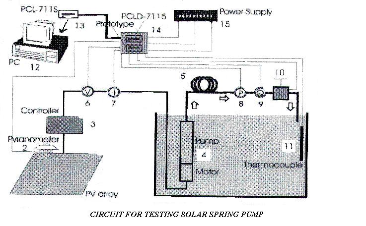
Description of testing circuit
TESTING CIRCUIT
Solar Spring pump (1) (WITHOUT SUNPRIMER ELECTRONICS unless the test rig is directly connected to PV panels!!) in tank (2) with power supply measured by volt-meter (3) and ampmeter (4). At least 10-20m of polyethylene feed pipe (5). An expansions tank (6) which serves to absorb residual pulsations and simulate free outlet as in normal field installations. Pressure measurement (7). Pressure regulating valve (8). Flowmeter (9). Current from PV panels should be measured as well as water flow. Currents and voltages relating to given water flows should be recorded, because even if they are not immediately useful, they can be used later on for study purposes to understand the phenomena in play and help with diagnosis of eventual problems.
Special WARNING concerning testing instruments
The response time of most cmmonly used instruments such as ampmeters and voltmeters is too slow to measure the reactions of the Sunprimer electronics accurately.
GOT TO: INSTALLATION INDEX
FOR MORE INFORMATION ON THE SOLAR SPRING PUMP PLEASE GO TO
SOLAR SPRING COVER PAGE
RETURN TO:PRODUCTS OFFERED
If you cannot find the information you require on these pages, please contact Terry Manning
by e-mail on : pumps@flowman.nl or
telephone or fax him at 0031-227-604128.
E-mail Terry Manning