Director,
T.E.(Terry)
Manning,
Schoener 50,
1771 ED Wieringerwerf,
The
Tel:
0031-227-604128
Homepage:
http://www.flowman.nl
E-mail: (nameatendofline)@xs4all.nl : bakensverzet
Incorporating
innovative social, financial, economic, local administrative and productive
structures, numerous renewable energy applications, with an important role for
women in poverty alleviation in rural and poor urban environments.
"Money is not
the key that opens the gates of the market but the bolt that bars them"
Gesell, Silvio The
Natural Economic Order
Revised English
edition, Peter Owen, London 1958, page 228
Edition 10:
List
of illustrations.
DRAWING OF WATER SYSTEM STRUCTURES.
WELL COMMISSIONS
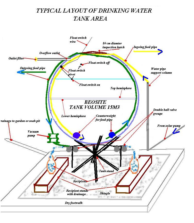
DRAWING OF TYPICAL WATER TANK AREA.
The structures necessary for
clean and sufficient drinking water supply are the ones calling for the
heaviest input in terms of formal capital. The structures will be set up during
the course of a Moraisain organisational workshop which will follow the
formation of most of the other structures foreseen. The following indications
will be subject to modifications, some of them substantial. They will, however,
give an idea of the dimensions of the project.
There are no existing wells
in the villages/areas in question so wells will have to be be dug and lined, or
boreholes drilled and lined where necessary. The wells should be sited as close
as possible to the users. The water then has to be pumped through pipelines
from the wells to above-ground tanks situated near the users' houses, so that
no-one need go more than 150m from home to fetch water.
The solar pumps are capable
of carrying water under pressure over several kilometers. Multiple small
high-efficiency pumps in place of larger (but much less efficient) ones are
proposed to guarantee a safe constant water supply. If one pump needs
maintenance, or if one water pipeline is accidentally damaged, the other pumps
continue working.
Taking the project area into
account, water should be found at a maximum depth of +/- (number) m. On average
the water table should be at (number) m. below the surface.
Water quality must be checked and water sourced from deeper aquifers if necessary.
The wells will normally be
2m outside diameter and 1.8m internal diameter.
Should it be necessary to
drill boreholes, the per person costs for the wells may be higher than the
figures shown in the indicative budget.
The wells must be well
protected against soil instability, using linings locally made in gypsum composite products factories
which are an integral part of the project. The wells must be sealed so that
surface water cannot flow back down the well. Hand pumps and platforms must be
built so that the users' feet remain dry and never come in contact with water.
Access to the handpumps/wells must always be dry. For instance, shingle or
similar materials can be used so that users' feet always remain dry.
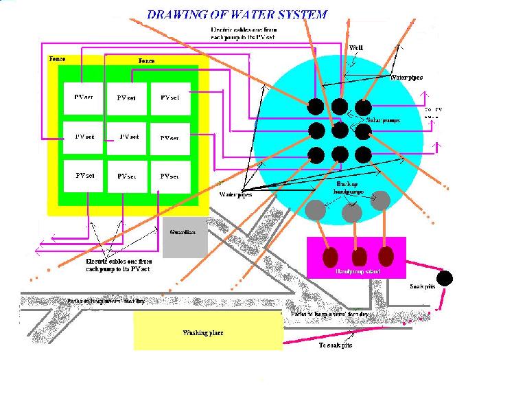
The layout of a typical well
installation is shown in: DRAWING OF WATER SYSTEM STRUCTURES.
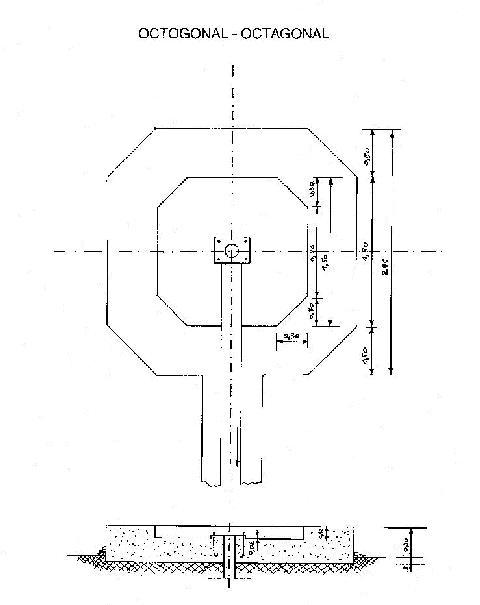
Hand pump platform.
The
choice of hand pumps should be such that hand pump platforms do not need to be
placed directly over the well or borehole, but at an appropriate point near or
at a distance from it.
Illustration
of a recommended hand pump platform.
List of drinking water requirements.
The assessment of drinking water requirements is carried out on the
basis of an average distance not exceeding 10-200 meters between each home and
a drinking water point. A basic drinking water supply of at least 25 litres per
person per day is foreseen. A further 25 litres per person per day is usually
made available as a back-up at protected boreholes and wells, which are placed further away. The project also provides for domestic
rainwater harvesting systems designed to supply an extra 25 litres per person
per day of non-potable water for personal uses such as washing and cleaning.
Water is not required for sanitation purposes, as dry composting eco-sanitation
toilet systems are expected to be used.
Example
of calculation of drinking water requirements.
(Village name).
See map (refer to map in the maps files).
a)
Inhabitants.
(number) family
groups, (number) population.
Drinking water supply
required @ 25 litres per person
per day = (amount) liters/day.
b)
Source of nearest electricity supply.
c)
Available clean drinking water supply (boreholes)(wells)(handpumps).
d)
Social structures.
There are also:
(number) Primary
schools
--How many children? By day?
Resident?
--Is the
school already supplied with water? Give details
--Is the school connected to the
electricity network?
(number) Intermediate schools
--How many children? By day?
Resident?
--Is the school
already supplied with water? Give details
--Is the school
connected to the electricity network?
(number) Hospitals/clinics
--Number of beds?
--Number of nurses
and doctors
--Daily number of
visitors?
--Existing water
supply?
--Connected to
electricity network?
--Water
requirements??
(number) Tourist attractions.
--Number of persons present
--Existing water supply?
--Connected to electricity
network?
--Water requirements??
(number)
Market places.
--Number of persons present? How often? How long?
--Existing water supply?
--Connected to electricity
network?
--Water requirements??
(number)
Churches, mosques, temples
(Description of use)
e)
Adaptation existing water supply?
How can existing water supply structures be brought within the project
structures?
Are there any ownership restrictions?
How can they be solved?
f) New drinking water
supply.
From several (number)
large diameter wells or boreholes, pump a total of (amount)m3 of drinking water
per day.
g) Siting of boreholes/wells.
(List indicative sites
of each well or borehole).
h) Pump
installations in each well or borehole.
Each well with (number)
Solar Spring (or a suitable alternative) high pressure solar pumps, for
a total of (number) solar pumps for all of the wells and boreholes together.
The solar pumps installed in each well are dedicated according to the
following criteria:
1.
One
solar pump dedicated to a water tank installation supplying each (number,
usually 200-300) users, being (number,
usually 40-50) families.
2.
Schools
in each well commission area : one solar pump dedicated to a drinking water tank installation for
each school.
3.
Clinics
in each well commission area : TWO
DEDICATED PUMPS each serving one drinking water tank with (at least 15m3 per
day).
4.
Important
market places, tourist attractions,
public buildings. Separate systems may be installed where the number of
users justifies them.
Each well with triple unit inertia (or alternative hydraulic) back-up
handpump-system next to it, for a total of (number) hand pumps for all of the
wells and boreholes together. In wells or boreholes serving very small
communities, a single unit back-up handpump may be sufficient.
i) The average expected distance between
each well or borehole listed in f) and the solar pumps installed in it in g) is
: (number) metres.
j) Description
of each well or borehole system.
-
The
well or borehole itself.
-
(Number)
solar pumps with accompanying electronics.
-
Photovoltaic
panel sets being ( indicate peaks watts to be installed – usually 300-400 Wp) (number (usually 4 panels
with a nominal rating between 75 and 100Wp) for each solar pump isntalled,
together with panel support fitted with a multipoint handtracking system.
-
Fence
or similar around PV panel installations.
A triple handpump system as backup. (In very small communities a single unit
back-up handpump may be sufficient.)
-
A
hand pump platform.
-
A
washing place.
-
Sink
pits for water drainage.
-
Paths
for users, whose feet must always remain dry.
-
Simple
accommodation for guardians.
-
Any
other buildings for well-commission level services which may be installed in
the well or borehole area. An example of these is the local money system
transaction registration units.
-
Any
communal gardens for the recycling of waste water run-off.
k)
Description of each drinking
water tank installation.
l)
Well commission ownership.
Ownership
of the following structures is vested in each well commission:
-
The
ground where the well or borehole installations are placed.
-
The
well or borehole itself.
-
The
fence or similar around PV panel installations.
The back-up hand pump system.
-
The
hand pump platform.
-
The
washing place.
-
The
sink pits for water drainage.
-
The
paths for users, whose feet must always remain dry.
-
The
simple accommodation for guardians.
-
Any
ground and communal gardens used for the recyling of waste water run-off.
The following drawings and graphs form an integral
part of this project proposal.
Refer
to list of maps
Summary
of water supply (example)
Inhabitants
: 47495
Boreholes : 32
Approximately litres/day 1.296.000 (1296 m3)
Solar pumps installed : 189
Installed photovoltaic power : 56.7 KW
15 m3 water tanks :189
Back-up hand pumps : 96 being 32 triple sets.
Pipelines from boreholes to water tanks
(estimation) : 200000m.
List of files on hygiene education, water
supply and sanitation.
List of drawings and graphs.
Typical list of maps.
List of key words.
List of abbreviations used.
Documents for funding
applications.