Director,
T.E.(Terry)
Manning,
Schoener 50,
1771 ED
Wieringerwerf,
The Netherlands.
Tel:
0031-227-604128
Homepage:
http://www.flowman.nl
E-mail:
(nameatendofline)@xs4all.nl : bakensverzet
Incorporating
innovative social, financial, economic, local administrative and productive
structures, numerous renewable energy applications, with an important role for
women in poverty alleviation in rural and poor urban environments.
"Money is not
the key that opens the gates of the market but the bolt that bars them"
Gesell, Silvio The
Natural Economic Order
Revised English
edition, Peter Owen, London 1958, page 228
Edition 6: 03 April,2010
INSTALLATION OF SOLAR SPRING PUMPS
The following pages are about the Sunprimer controller
and how to mount the Sunprimer controller on the support structure. If you are more
interested in other aspects concerning installation, please return to the installation index.
WARNING! If your PV array is left disconnected in the
full sun in open circuit condition, voltage may rise to anything up to 100V
even in cloudy weather, enough for a nasty shock. When working on the array
output wiring you may leave one wire disconnected between two of the modules to
break the circuit, or shade the array by turning it out of the sun or by
covering it.
An array on/off switch may be placed between the array
and the controller, NEVER between the controller and the pump. Any good quality
water-tight 30 amps single phase switch will do the job. This switch will
always be left in "ON" mode, and will be switched off only during
installation and maintenance. If there is no array disconnect switch, then
BEFORE TOUCHING ANY WIRES make sure your array is turned away from the sun or
that it is covered so as to reduce all risk of serious shock.
Simple controllers called "boosters" are
available in commerce for use with PV panels. They are valid and useful for
most applications. They are essentially voltage or current transformers or
inverters and serve to improve the coupling ratio between PV panels and the
devices being used. HOWEVER THEY ARE NOT SUITABLE FOR USE WITH HIGH PERFORMANCE
SUBMERSIBLE HORIZONTAL AXIS PISTON PUMPS which have to be able to start under
load. For this purpose more complex devices such as the Sunprimer units are
required, with devices capable of starting the pump under and protecting the
motor when the pump is not working.
The Sunprimer electronics unit incorporates five
functions:
1) To interrupt current connection between the
PV panels and the pump when irradiation or the battery charge is such that voltage is
so low (with the Sunprimer MK II
unit it is about 22V) that the pump slows down to the point where it stops.
This stops the motor from being put under continuous load when stopped.
2) To start your Solar Spring pump as early as
possible in the morning and keep it going as long as possible into the evening
(thus extending running time), provided irradiation or battery charge is
sufficient to keep the pump running. If the pump cannot start, or is turning
too slowly, function 1 enters into operation. If irradiation is reasonable,
function 2) will make another attempt to start the pump. A secondary timer unit
attempts to start the pump at intervals of approximately two minutes. This
timer also operates on initial starting up, so that the pump will start operating
APPROXIMATELY TWO MINUTES (Mk II) AFTER ELECTRICAL CONTACT HAS BEEN MADE.
3) To switch nominal voltage between 48V and
24V in relation to the available power from the PV panels and pump load, so as
to optimise amperage absorbed by the pump motor and adjust motor speed as
required to optimise pump capacity. This enables the pump to operate better in
slightly cloudy conditions and/or earlier in the morning and later in the
evening. This device performs some of the functions of traditional "boosters".
The Sunprimer MK II controller always charges the capacitor to 60V even in 24V
and battery applications. The Mk II controllers start in 24V mode, then switch
to 48V if sufficient current supply is available.
4) To connect the Solar Spring pump to GOOD
QUALITY external float switches and/or other devices such as pre-sostates. This
is the smallest cable which comes out of the Sunprimer. It has two wires which,
when placed in contact with one another or in an electrical circuit, interrupt
the electricity supply. When the two wires are not in contact with one another
or in an electrical circuit, the controller feeds current to the pump motor
and, assuming irradiation is sufficient, the pump will start again after about
three minutes. The external controls or switches used should be of high quality
and such that on and off contacts be made cleanly, precisely and quickly.
Uncertain or irregular contacts may damage the controller.
5) To save pump motor and system components
where specifications are not complied with during installation and/or in the
presence of particular extreme or unforeseen environmental events (including
freezing or blocking of the feed pipe system for any other reason or excessive
draw-down of water in the borehole) where a fail-safe system is needed. For
instance this function intervenes to cut current where current is greater than
4.5 amps for more than half a second. Normal starting procedures will then be
activated, so the pump will attempt to start again after approximately two minutes (Mk II).
6)Another device will act to cut current to the
controller by putting the PV panels into short circuit when for any reason the
main transistor in the controller is damaged so that the controller can no
longer work properly. The pump will automatically start again once the damaged
transistor has been repaired.
7) The Sunprimer Mk II controller does not have a minimum current control to switch
the pump off where it is running dry. The pump can run dry for days or even
weeks without suffering undue harm. It has been assumed that where dry running
is not immediately obvious to users, those interested will carry out periodic
checks to make sure the pump is in fact pumping water.
The Sunprimer unit is to be mounted VERTICALLY with
CABLE OUTLETS TOWARDS THE BOTTOM on to the rear side of the lower panel
support. Although the controller is hermetically sealed against water, sand,
and weather conditions generally, it is good practice to place it in as
protected an environment as possible, sheltered so far as possible against rain
and the direct rays of the sun. Although the Sunprimer is equipped with
internal protection mechanisms tending to avoid momentary faulty connections
and inversions of polarity, electrical connections should be made very
carefully. SHORT CIRCUITING SHOULD BE AVOIDED. NEVER put wires in short circuit
to see whether they produce sparks as is sometimes done with motor vehicle
batteries. Where the array is placed a long way away from the water source, it
is preferable to site the controller separately, appropriately sheltered from
heat and the sun's rays, closer to the water source. In case of doubt, please
consult your supplier.
WARNING! DO NOT MOUNT THE CONTROLLER DIRECTLY
AGAINST PV PANELS. PV panels become hot when exposed to the sun. If the
controller is mounted in direct contact with PV panels, the heat from the
panels can be transferred through the controller box to the electronics
environment of the controller. This may damage the controller. Where the controller
is to be placed next to PV panels suitable heat insulation material must be
inserted between the PV panel and the controller to avoid passage of heat from
the PV panel to the controller.
The controller incorporates a self-diagnostic circuit
which helps detect faults during installation and maintenance. The LED lights
can be seen when the back of the controller box is removed by undoing the four
controller box screws.
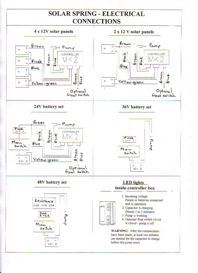
The LED lights are numbered in LOGICAL CIRCUIT
ORDER, in order from the top 4,2,1,3
The first LED, the third from the top, (shown in the
drawing as no. 1) lights up when a voltage greater than about 10V reaches the
controller from the panels.
The second LED, the second from the top, (shown on the drawing as no. 2) lights
up when the main capacitor is charging. This phase lasts about three minutes
with the Mk I/d and Mk I/e controllers and about 2 minutes with the Mk II
controller. Note that in certain circumstances the capacitor may be impeded by
built in safety mechanisms from charging.
The third LED, the one at the bottom, (shown on the drawing as no. 3) lights up
when the controller sends output voltage greater than about 10V to the pump
motor.
The fourth LED, the one at the top, (shown on the drawing as no. 4) lights up
when the pump motor stops because the external (float) switch is in OFF mode.
For more information on the LED lights refer to
USE OF CONTROLLER DIAGNOSTICS
Despite the presence of defence mechanisms built into
the Sunprimer units, the manufacturer's guarantee is voided where voltages
higher than those prescribed are used, even if such voltages are applied for a
very short period of time. Nor does the manufacturer's warranty cover the use
of the Sunprimer with power generators not being photovoltaic generators, nor
does it cover infiltration of water or external overheating whether of solar or
other origin. Consult your supplier BEFORE carrying out laboratory testing, for
which instructions will be given to interested parties.
THE CONTROLLER ITSELF MAY BE DAMAGED IF
VOLTAGES HIGHER THAN THOSE PRESCRIBED ARE USED.
THE PUMP MOTOR WILL BE DAMAGED IF CURRENT IS
NOT CUT WHEN THE PUMP IS NOT WORKING.
The product guarantee for Solar Spring pumps
and/or Sunprimer controllers does not cover use with generators, even for a
very short time, other than PV panels and batteries, whether for testing
purposes or otherwise. Nor does the warranty extend to use of the products with
voltages and/or currents greater than those specified for normal conditions of
use with 24V PV or battery systems or with 48V PV panels systems using 4 panels
each of 12V nominal voltage as prescribed. Nor does the warranty cover loss or
damage directly or indirectly caused by lightning, water infiltration or
externally caused overheating whether of solar or other origin.
For information on lightning protection please
return to the installation index.
AVOID leaving coils of surplus electric cable
on-line at the well-head or elsewhere, as these have been known to cause
secondary inductive current and on rare occasions confuse controller
components.
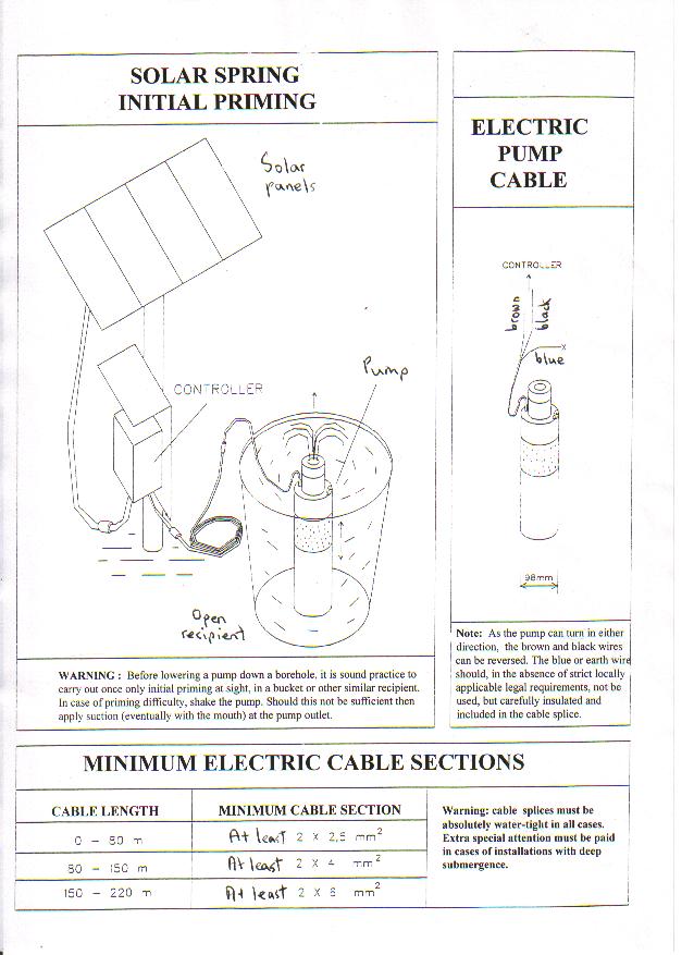
It is good practice to run the pump with an open head in
a recipient for a few minutes to make sure the valves are not stuck, BEFORE
proceeding with the installation of the pump. For a drawing, refer to:
ILLUSTRATION OF INITIAL PRIMING PROCEDURE.
Please refer to WHAT TO DO IF THE
VALVES ARE STUCK for a description of the procedure to follow.
1) The Mk II Sunprimer works without adjustment with
48V and 24V arrays and 24V battery installations.
2) If the Sunprimer box has been opened, make sure the box sealing ring is
correctly in place when it is closed.
The SMALLEST is to be connected to eventual external
switches such as float-switches, pre-sostate or pressure control groups etc.;
the MIDDLE-SIZED cable (or outlet cable), which is to be connected to the pump,
the LARGEST (or inlet cable) which is to be connected to the panels. If the
smallest cable is not used, the ends of each of its two wires must be
separately carefully insulated.
DRAWING OF CONNECTIONS FOR THE
SUNPRIMER MKII
The Sunprimer outlet cable has two wires, one
BROWN (POSITIVE) and one BLUE (NEGATIVE). This has to be connected to the PUMP.
With all 4" diameter pumps the cable from
the pump has three wires, brown, black, and blue.
1)THE BROWN OF THE SUNPRIMER IS CONNECTED WITH THE
BROWN OF THE PUMP. Since the pump motor can run in either direction, the BROWN
of the Sunprimer can also be connected to the BLACK of the pump.
2)THE BLUE OF THE SUNPRIMER IS CONNECTED WITH THE
BLACK OF THE PUMP, Since the pump motor can run in either direction, the Blue
of the Sunprimer can also be connected with the Brown of the pump.
3)THE BLUE OF THE PUMP IS THE EARTH WIRE AND IS
TO BE CONNECTED TO EARTH OR WELL INSULATED AND NOT USED, ACCORDING TO APPLICABLE
ELECTRICAL NORMS. The blue wire is supplied only to meet the requirements of
eventually applicable electrical safety standards. We recommend the earth be
used ONLY WHERE it's use cannot be avoided. We believe it INCREASES risk of
damage and that it can cause electro-galvanic corrosion phenomena.
FIRST, TO AVOID RISK OF SHOCK MAKE SURE YOUR ARRAY IS
NOT IN OPEN CIRCUIT! Turn it away from the sun, and/or cover it and/or
disconnect one wire between two modules.
THEN CONNECT THE SUNPRIMER TO THE MOTOR AS
ALREADY DESCRIBED ABOVE.
DRAWING OF CONNECTIONS FOR THE
SUNPRIMER MKII
The larger cable coming out of the bottom of
the Sunprimer unit is the inlet cable and it has to be connected to the
photovoltaic panels.
It has FOUR WIRES, brown, black, blue, and
green-yellow.
WHERE YOU ARE USING FOUR STANDARD PANELS EACH
WITH 36 CELLS WITH 12V NOMINAL VOLTAGE AND A WORKING VOLTAGE FROM 14-17V AND AN
OPEN CIRCUIT VOLTAGE FROM 18V-21V open circuit voltages can reach 100V.
Panels with 72 cells are now commercially available.
These are usually made by mounting two standard panels each with its own
electrical clips in the same frame. Extra attention should in such case be paid
to the electrical contacts because of the risk of getting the electrical
contacts of each of the two single panels mixed up.
Panels with a nominal voltage of 6V can of course also
be used provided they are grouped in lots of 24V as prescribed.
The four photovoltaic panels are ideally divided into
two pairs and the panels of each pair are connected in series with 24V nominal
voltage.
DRAWING OF CONNECTIONS FOR THE
SUNPRIMER MKII
The POSITIVE of the first pair of panels is connected
to the BROWN wire of the Sunprimer. The NEGATIVE of the first pair of panels is
connected to the BLACK wire of the Sunprimer.
The POSITIVE of the second pair of panels is
connected to the BLUE wire of the Sunprimer unit. The NEGATIVE of the second
pair of panels is connected to the YELLOW-GREEN wire of the Sunprimer.
If the connections are incorrectly made, or if the two
pairs of panels are different from one another or exposed to the sun in a
different way, the system MAY NOT WORK at all or may not work properly.
The Sunprimer will start the motor about two minutes
after the circuit has been completed.
WHERE YOU ARE USING TWO PANELS with a Mk II controller:
DRAWING OF CONNECTIONS FOR THE SUNPRIMER MKII
Connect the pump to the controller as for 48V installations.
Then first connect together the brown and blue wires of the largest
cable coming out of the controller, then connect the two panels in series so as
to obtain 24V nominal, then connect the positive of the pair of panels to the
combined brown and blue controller wires.
Then connect negative of the panels to the yellow/green controller wire.
Carefully insulate the black controller wire, which is not used.
The small float switch cable coming out of the controller is wired as
for 48V installations.
General single- or two-pole on-off switches may if
considered necessary be fitted on the positive wires (or on the positive and
negative wires) of the panels. NEVER, NEVER insert any switch or other control
device between the Sunprimer and the pump.
Please consult the manufacturer.
DRAWING OF CONNECTIONS FOR THE SUNPRIMER MKII
A general single- or two-pole switch must be fitted to the positive (or
to the positive and the negative) of the battery set.
INSERT TWO GOOD QUALITY 3 AMP FUSES (they are not supplied with the
pump) in series on the positive (combined brown and blue) wire between the
battery set and the controller. A standard motor vehicle fuse is appropriate.
Connect the pump to the controller as for 48V installations.
Then first connect together the brown and blue wires of the largest
cable coming out of the controller, then connect the two panels in series so as
to obtain 24V nominal, then connect the positive of the pair of the battery set
to the combined brown and blue controller wires.
Then connect negative of the battery set to the yellow/green controller
wire.
Carefully insulate the black controller wire, which is not used.
The small float switch cable coming out of the controller is wired as
for 48V installations.
The product warranty does not cover damage caused by failure to install
an on-off switch or a fuse or by the failure of such switch and fuse to work
properly.
For extra safety it is recommended that two identical fuses be mounted
in series.
To ensure optimum battery duration a good quality automatic system for
the control of battery charging and discharging cycles including LVD (Low
Voltage Disconnect) should be installed, in particular to avoid excessive or
long duration battery discharge conditions. The pump should work only when the
battery set is appropriately charged and should be switched off when the set is
discharged. The Mk II controller incorporates a device which switches the pump
off should the input voltage go down to about 22V. This device should be
considered a second line of defence and does not substitute correct manual or
automatic management of battery use.
The Solar Spring pump may be connected WITHOUT
CONTROLLER to 36V nominal battery sets in cases where special current surge for
start up is not required.
Do not use pumps with 3mm or 2.6mm cams for battery
applications without controller. This is because:
a) 3mm pumps need 56V on start up.
b) Commercial fuses are inaccurate and may take
some time to react
TWO GOOD QUALITY 3 AMP
SAFETY FUSES (they are not supplied
with the pump) MUST BE FITTED in series on the positive (combined brown and
blue) wire between the battery set and the controller. Standard motor vehicle
fuses are appropriate.
The product warranty does
not cover damage caused by failure to install an on-off switch or a fuse or by
the failure of such switch and fuse to work properly.
Electric connection on start
up MUST ALWAYS BE INSTANTANEOUS. If the connection is gradual and progressive,
the pump may not start, and in this case high short circuit current conditions
would occur with the pump stopped, and this would burn out the fuse.
ALWAYS test the pump with
general switch and safety fuses already fitted.
Refer to comments under 24V battery systems concerning measures supporting
optimum battery duration.
This is because:
a) 3mm pumps need 56V on start up.
b) Commercial fuses are inaccurate and may take
some time to react
48V battery installations are potentially dangerous in that excessive surge
current can be generated unless appropriate steps are taken to avoid risk of
demagnetisation of the motor and rapid wear and tear of the motor brushes.
In addition to the general switch and the fuse mentioned for 36V battery
installations, 48V battery systems must also have both in actual installations
and during eventual tests an electrical resistance OF AT LEAST 0.68 Ohm to act
as a limiter. This can be installed by inserting between THE BATTERY AND THE
PUMP a 0.68 Ohm 25W resistor. The resistance of the electrical cable itself is
sufficient for this purpose provided AT LEAST 50 meters of 2.5mm2 cable or AT
LEAST 80 meters of 4.0mm2 cable or AT LEAST 120 meters of 6mm2 cable is
installed.
Installation of systems with battery sets over 48V
nominal voltage is PROHIBITED.
Although the system will work more efficiently with 4 panels, the Mk II
Sunprimer can also be used with 3 panels.
The panels have to be connected in series as for two
panels.
The configuration uses the full power of all
three panels, but (just as is the case for use with 2 panels) it does not use
the series/parallel switching mechanism.
The system will therefore operate for fewer
hours per day, and the system will operate slightly less efficiently than it
would with 4 panels. The initial
starting power is the same as it would be if there were just two panels, but
the normal working power is that of three panels.
Conditions of use lie between those for two
panels and for four panels. In typical conditions you would use 3mm cam with 4
panels (with the Hyboost) and 2.2mm cam with 2 panels (without the Hyboost).
So, you would use in this case a pump with a 2.6mm cam without the Hyboost unit
with panels > 70Wp. If the panels were smaller it would be better to use a
smaller cam. If you try to use a 3mm cam with Hyboost with 3 panels, you will
not harm the pump, but the system is going to start later in the morning,
finish earlier in the evening, and it may stop completely when clouds go over.
It will therefore pump more water when irradiation is good but less water over
the whole day. It would therefore globally speaking operate less efficiently.
If certain types of high-voltage modules now being
introduced to the market are used with the Sunprimer in very cold areas, there
is a risk that AT CELL TEMPERATURES below -5 degrees C. it be advisable to
install a voltage limiter between the panels and the Sunprimer unit.
Some
recommended technologies.
List of
attachments to the Model.
Typical list of graphs and
drawings.
List of abbreviations used.
List of key words.
Documents for funding
applications.