Director,
T.E.(Terry)
Manning,
Schoener 50,
1771 ED
Wieringerwerf,
The
Tel: 0031-227-604128
Homepage:
http://www.flowman.nl
E-mail:
(nameatendofline)@xs4all.nl : bakensverzet
Incorporating
innovative social, financial, economic, local administrative and productive
structures, numerous renewable energy applications, with an important role for
women in poverty alleviation in rural and poor urban environments.
"Money is not
the key that opens the gates of the market but the bolt that bars them"
Gesell, Silvio The
Natural Economic Order
Revised English
edition, Peter Owen, London 1958, page 228
Edition 9:
The following pages contain information on how to fit
the feed pipe, the rapid coupling, and (where a pump with a 3mm cam shaft is
being installed) the Hyboost inertia amplifier. If you are more interested in
other aspects concerning installation, please return to the installation
index.
Note : Before fitting the feed pipe to the pump it is
wise practice, where possible, to operate the pump for a few minutes without
any outlet pipe in a recipient of water, to check priming. The valves, may,
after storage, be "stuck", and the pump may require some time to
expel air from its system. Shaking the pump can help get air out. In very rare
cases it may be necessary to apply suction at the outlet.
Note : Feed pipe should be as specified. Do NOT use PVC piping. It is
rigid and above all made from highly toxic material. Use 3/4" 25mm OD 18mm
ID nominal pressure PN16 bar sanitary polyethylene pipe. Nominal pressure PN10
polyethylene pipe may be used in shallow installations up to a maximum of 30m
head.
Establish or re-check carefully the length of feed
pipe needed. The feed pipe should be long enough for the pump to be installed
about 10m BELOW the estimated lowest seasonal water level in the bore-hole,
taking also into account the amount of water to be pumped and the actual
capacity of the bore-hole. Should there be risk of substantial lowering of the
water level in the bore-hole during the day ( in this case pump capacity is
greater than the bore-hole capacity) the pump should be placed well below the
minimum daily water level. If there is in such case insufficient replenishment
of water in the bore-hole at night, then the size of the PV array must be
adjusted to the capacity of the bore-hole to avoid all risk of not having any
water at all.
IN ANY CASE CHECK AND RECORD THE LEVEL OF THE WATER IN THE BOREHOLE !
The feed pipe must also be long enough to reach the point of water
discharge, whether this is an open trough or similar, or a storage tank or
other recipient. The feed pipe should wherever possible be FREE FROM RISK OF
DAMAGE by vehicles, animals, people, or machinery. It is wise to embed the
length of feed pipe outside the bore-hole.
The feed pipe is usually supplied in rolls of 100m.
The characteristics of the Solar Spring pump are such that more than one
complete roll of feed pipe may be necessary. In this case, double feed-pipe
joints are available to join two lengths of feed pipe together. Such double
joints are also made following the procedures now described for a situation
where a roll of feed pipe has to be cut because the length required is less
than 100m.
Once the length of feed pipe required has been measured, cut the pipe
with a knife or hacksaw, making sure the two ends of the feed pipe are straight
and smooth. Ragged cuts may cause defective grip and loss of water from the
system.
Feed pipe edges must be straight and smooth.
The rapid couplings supplied with the pump are
designed to take 3/4" (25mm outside diameter and 18mm internal diameter)
polyethylene drop pipe with a nominal pressure rating of 16 bar. Should for any
reason any other pipe size or coupling need to be used, please consult your
supplier BEFORE attempting to use them.
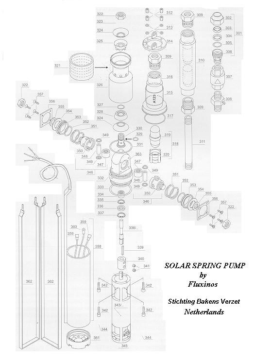
The rapid coupling (part 301) is made up of 5 parts :
Part 306 (body) which is usually already firmly screwed on to the outlet or on
to the foot valve (307) at the top of the pump or of the Hyboost inertia unit
Part 305 (coupling "O" ring)
Part 304 (press ring)
Part 303 (polymer clinching ring)
Part 302 (coupling head)
Parts 302,303,304,and 305 (if the pump is new, they have NOT been
tightened) must be unscrewed by hand and then fitted on to the feed pipe. Careful
attention must be paid to the order and to the direction of each piece.
Push pieces 302 (head) backwards on the feed pipe with
the screwed part towards the end of the pipe, 303 (white clinching ring) with
its more rounded side against the top of part 302 and its CONICAL SIDE towards
the thread of part 302, then part 304 (brass press ring) with its CONICAL SIDE
against the CONICAL side of the white clinching ring 303 and its flat side
towards the thread of part 302 (head) and finally "O" ring part 305
about 3cm up the feed pipe. Then push the feed pipe with parts 302,303,304,and
305 on it as far as possible into its seat in the coupling body (306).This
distance is about 2cm as the entry of the feed pipe into the coupling body
(306) is stopped by a step inside the body (306) itself. Move the "O"
ring (305) down the feed pipe so that it is completely seated at the coupling
body entrance (306). You may find it helpful to position the "O" ring
(305) about 1cm from the end of the feed pipe before pushing the feed pipe into
the body (306).
The press ring (304) is positioned with its conical
face against the conical face of the white clinching ring (302).
The clinching ring (302) is positioned with its internal teeth directed against
the movement of the feed pipe, so that as the feed pipe tends to move, the
teeth grip more deeply into it.
Tighten the coupling head 302 over coupling body 306 first by hand and
then tighten it firmly using a spanner.
The Hyboost inertia amplifier is used only with 3mm cams.
Solar Spring units with 3mm cam are supplied with the
Hyboost inertia amplifier packed separate from the pump, but ready for
immediate assembly. The free end of the Hyboost pipe (part 311) already has
teflon tape on it and the Hyboost is simply firmly screwed into its seat (309).
In this case the elastic element (319) with its seat (320) have already been
removed at the factory.
If the Hyboost unit is to be used with a pump NOT already fitted with a 3mm
cam, then it will be necessary FIRST to change the cam size of the pump,
SECONDLY to remove the elastic element (319) and its seat (320) from the
existing pump system, and THIRDLY fit a Hyboost unit. Change of cam size by
persons not familiar with Solar Spring pumps is NOT RECOMMENDED and must be
AVOIDED.
If the pump is already fitted with a 3mm cam and an elastic element 319 and
element seat 320, but not with a Hyboost, then:
Remove the rapid coupling (301) with foot valve (307) and nipple (part 308)
from the top of the pump group outlet.
Remove the outlet group (parts 213 to 320) from the valve group by unscrewing
the 4 nuts (part 312)
Remove the ovoid (part 319) and the centering piece (part 320) from the outlet
group.
Replace the empty outlet group on the pump and tighten nuts (part 312)
Firmly tighten the free end of the metal pipe (311) of the Hyboost group into
part 309 at the top of the pump outlet group (parts 312 to 317)
Replace in order, the nipple (308), the foot valve (307), and the rapid
coupling (301) by fitting them in part 309 on top of the ovoid chamber of the
Hyboost unit (part 310). Teflon tape should be used at each joint. Remove the
old tape and use new tape !
Keep the ovoid (part 319) and the centering piece (part 320) carefully. They
could be useful to you later on.
Sunprimer Mk II controllers detect abnormal build up
of system pressure and automatically switch the pump off to protect both pump
system and feed pipe. However, a pressure relief valve may be fitted on the
feed pipe above the pump or above the Hyboost. It serves to avoid damage to the
feed pipe where the feed pipe gets blocked either by the improper installation
and/or use at any point along the feed pipe of a stop valve of cock or in case
of blocking of the feed pipe due to external causes while the pump is in
operation. The pressure Solar Spring pumps are able to develop is greater than
that of the feed pipes recommended, and should the feed pipe be blocked the
feed pipe may suffer serious damage. The operating pressure of the relief valve
should be 25% lower than the nominal pressure of the feed pipe used.
Menu installation Solar Spring pumps.
Some recommended technologies.
List of attachments to the Model.
Typical list of graphs and
drawings.
List of abbreviations used.
List of key words.
Documents for funding
applications.