Director,
T.E.(Terry)
Manning,
Schoener 50,
1771 ED
Wieringerwerf,
The
Tel: 0031-227-604128
Homepage:
http://www.flowman.nl
E-mail:
(nameatendofline)@xs4all.nl : bakensverzet
Incorporating innovative
social, financial, economic, local administrative and productive structures,
numerous renewable energy applications, with an important role for women in
poverty alleviation in rural and poor urban environments.
"Money is not
the key that opens the gates of the market but the bolt that bars them"
Gesell, Silvio The
Natural Economic Order
Revised English
edition, Peter Owen, London 1958, page 228
Edition 9:
The valve group comprises the valve chamber (326) together with the
lower valve group and the upper valve group.
In pumps with series numbers up to and including B531, the lower valve
group comprises the lower valve rubber (324), the lower valve rubber support
(328) the valve spindle (330) the lower spindle ring (329) and the upper
spindle ring (327)
The
upper valve group comprises the upper valve rubber support (325), the upper
valve rubber (324), the upper valve positioning ring (323) and the valve
spindle nut (322)
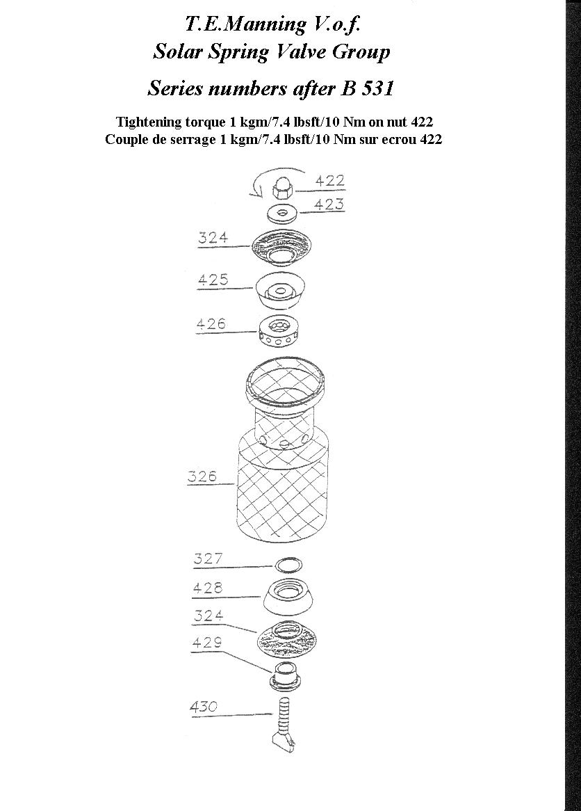
In
pumps with series numbers after B531, the lower valve group comprises the lower
valve rubber (324), the lower valve rubber support (428) the manual valve bolt
(430) the flanged retention ring (429) and the spindle ring (327)
The
upper valve group comprises the upper valve rubber support (425) with the brass
diffuser ring (426) usually attached to it, the upper valve rubber (324), the
upper valve positioning ring (423) and the valve spindle nut (422).
The only parts of the valve group (rarely) requiring replacement are the
valve rubbers. The valves may however on rare occasions "stick" if
they are not cleaned before being laid up for a long period. A description of
how to clean the valves in such cases is therefore given.
Tools required : Ring spanner size 22; vice; if available special valve
spindle tool (85)
Undo the valve spindle nut (322) in the top of the valve chamber (326)
and remove, in turn, off the valve spindle (330):
The valve spindle nut (322)
The positioning ring (323)
The upper valve rubber (324)
The upper valve support (325)
The valve chamber (326)
The upper spindle "O" ring (327)
The lower valve support (328)
The lower valve rubber (324)
The lower spindle "O" ring (329)
Undo
the valve nut (422) in the top of the valve chamber (326) and remove, in turn,
off the manual bolt (430):
The valve nut (422)
The positioning ring (423)
The upper valve rubber (324)
The upper valve support (425) with the diffuser ring (426) usually attached to
it
The valve chamber (326)
The upper spindle "O" ring (327)
The lower valve support (428)
The lower valve rubber (324)
The flanged retention ring (429)
Replace the valve rubbers.
Note : The valve rubbers need to be replaced only where they are showing cuts
or signs of advanced wear and tear evidenced by areas which are much thinner
than others. Valve rubbers can be expected to last more than ten years and wear
and tear on them is, in normal circumstances, minimal.
How to clean and maintain the valve rubbers.
In most cases where the valves have got "stuck" after storage to the
point that normal procedures are insufficient to free the valves again, it will
usually be sufficient to clean the valves and then reassemble them.
1)Flake rust and mud deposits off the valve rubbers and parts using the blunt
side of a screwdriver or some other appropriate instrument.
2)Clean the surface of the parts with water and a soft rag.
3)Apply a thin layer of Vaseline or similar non-toxic material to the surface
of the valve rubbers, especially if the pump is to be laid up for a period of
time.
4)It is not necessary to remove the Vaseline before the pump is next used.
5)Proceed with re-assembly as set out below.
The key piece for assembly is the valve spindle (330).
Place the spindle (330) with its wide end down, place the lower spindle
"O" ring (329) (this is the larger of the two spindle "O"
rings) on the spindle (330) making sure it is correctly placed in its seat,
then the lower valve rubber (324) with the wider rim pointing down, then the
lower valve support (328) with the wider rim pointing down (the lower valve
support (328) is easily distinguishable from the upper valve support (325) as
the lower support (328) is flat across its lower end, while the upper support
(325) has an indented seating), then the upper spindle "O" ring (327)
(this is the smaller of the two "O" rings) making sure the ring (327)
is correctly seated in the valve spindle (330).
Fit the valve chamber (326) over the lower spindle group, then the upper
valve support (325) with its narrow end down; then the upper valve rubber (324)
with its narrow end down; then the spacing ring (323) then the valve spindle
nut (322) with its narrow end down.
The key piece for assembly is the manual valve bolt
(430). Place the flanged retention ring (429) with its flange at the bottom on
the manual bolt (430) so that the flange is against the manual grip of the bolt
(430), then the lower valve rubber (324) with the wider rim pointing down, then
the lower valve support (428) with the wider rim pointing down (the lower valve
support (428) is easily distinguishable from the upper valve support (425) as
the lower support (428) has a much larger hole and the upper support (425)
usually has the brass diffuser ring attached to it, then the upper spindle
"O" ring (327) making sure it is correctly seated in the valve
spindle (330) in the space between the lower valve support (428) and the narrow
end of the retention ring (429)
Fit the valve chamber (326) over the lower spindle group, then the upper
valve support (425) with its narrow end (with the diffuser ring 426 fixed to
it) down; then the upper valve rubber (324) with its narrow end down; then the
spacing ring (423) then the valve spindle nut (422).
For pumps up to and including B531, firmly screw the valve spindle nut
(322) onto the valve spindle (330).
WARNING!! TORQUE ON VALVE NUT (322) IS 2KG. Over-tightening of valve nut (322)
can lead to breakage of valve spindle (330).
For pumps with series numbers after B531, firmly screw the valve nut
(422) onto the manual valve bolt (430) using an appropriate spanner.
WARNING!! TORQUE ON VALVE NUT (422) IS 1KG, or 7.4 lbs per square foot, or 10
Nm.
Menu for the maintenance of Solar Spring pumps.
Some recommended technologies,
List of attachments to the Model.
Typical list of graphs and
drawings.
List of abbreviations used.
List of key words.
Documents for funding
applications.