Director,
T.E.(Terry)
Manning,
Schoener 50,
1771 ED
Wieringerwerf,
The
Tel: 0031-227-604128
Homepage:
http://www.flowman.nl
E-mail:
(nameatendofline)@xs4all.nl : bakensverzet
Incorporating innovative
social, financial, economic, local administrative and productive structures,
numerous renewable energy applications, with an important role for women in
poverty alleviation in rural and poor urban environments.
"Money is not
the key that opens the gates of the market but the bolt that bars them"
Gesell, Silvio The
Natural Economic Order
Revised English
edition, Peter Owen, London 1958, page 228
Edition 5:
Un
controlador de la bomba es requerido para cualquier sistema de bombeo sin
baterías. Sin él, la bomba no arrancará apropiadamente, y se parará en
condiciones de baja luz.
No
intente hacer funcionar la bomba sin el controlador Sunprimer.
Una corriente inadecuada de arranque puede causar sobrecalentamiento del motor.
Coloque
el controlador en la sombra, de tal manera que no se ponga muy caliente con el
sol de medio dma. Montarlo abajo del arreglo AF es adecuado.
WARNING! If your PV array is left disconnected in the full sun in open
circuit condition, voltage may rise to anything up to 100V even in cloudy
weather, enough for a nasty shock. When working on the array output wiring you
may leave one wire disconnected between two of the modules to break the
circuit, or shade the array by turning it out of the sun or by covering it.
Un switch on/off debe estar colocado entre el arreglo AF y el controlador,
!NO sobre la línea que va a la bomba! Debe ser un switch de dos polos.
Conictelo para desconectar el positivo de cada mitad del arreglo solar.
Sugerimos un modelo QO-200TR Square-D (marca), "Switch de caja
moldeada cerrada", de su distribuidor elictréco, o de Graingers (modelo #
1H245). Es compacto y barato. O, puede usar un switch común AC de desconexión
para lluvia intensa, de valores nominales "30 amps.,una fase".
Vea el diagrama de cableado del controlador. Si no está usando el switch de
flotador, debe aislar el cable de tal manera que lo cables no entren en
contacto, o de lo contrario.
The
Sunprimer electronics unit incorporates five functions:
1) To interrupt current connection between the PV panels and the pump when
insolation and, with Sunprimer MK II, the battery charge is such that voltage
is so low (about 22V) that the pump slows down to the point where it stops.
This stops the motor from being put under continuous load when stopped.
2) To start your Solar Spring pump as early as possible in the morning and
keep it going as long as possible into the evening (thus extending running
time), provided insolation or battery charge is sufficient to keep the pump
running. If the pump cannot start, or is turning too slowly, function 1 enters
into operation. If insolation is reasonable, function 2) will make another
attempt to start the pump. A secondary timer unit attempts to start the pump at
intervals of approximately two minutes. This timer also operates on initial
starting up, so that the pump will start operating APPROXIMATELY TWO MINUTES)
AFTER ELECTRICAL CONTACT HAS BEEN MADE.
3) To switch nominal voltage between 48V and 24V in relation to the
available power from the PV panels and pump load, so as to optimise amperage
absorbed by the pump motor and adjust motor speed as required to optimise pump
capacity. The MK II Sunprimer controller always charges the capacitor to 60V
even in 24V and battery applications. The Mk II controllers start in 24V mode,
then switch to 48V if sufficient current supply is available.
4) To connect the Solar Spring pump to GOOD QUALITY external float switches
and/or other devices such as presostates. This is the smallest cable which
comes out of the Sunprimer. It has two wires which, when placed in contact with
one another or in an electrical circuit, interrupt the electricity supply. When
the two wires are not in contact with one another or in an electrical circuit,
the controller feeds current to the pump motor and, assuming insolation is
sufficient, the pump will start again after about three minutes. The external
controls or switches used should be of high quality and such that on and off
contacts be made cleanly, precisely and quickly. Uncertain or irregular
contacts may damage the controller.
5) To save pump motor and system components where specifications are not
complied with during installation and/or in the presence of particular extreme
or unforeseen environmental events (including freezing or blocking of the feed
pipe system for any other reason or excessive draw-down of water in the
borehole) where a fail-safe system is needed. For instance this function
intervenes to cut current where current is greater than 4.5 amps for more than
half a second. Normal starting procedures will then be activated, so the pump
will attempt to start again after approximately two minutes.
6)Another device will act to cut current to the contoller by putting the PV
panels into short circuit when for any reason the main transistor in the
controller is damaged so that the controller can no longer work properly. The
pump will automatically start again once the damaged transistor has been
repaired.
7) The Mk II controller does not have a minimum current control to switch
the pump off where it is running dry. The pump can run dry for days or even
weeks without suffering undue harm. It has been assumed that where dry running
is not immediately obvious to users, those interested will carry out periodic
checks to make sure the pump is in fact pumping water.
The Sunprimer unit is to be mounted VERTICALLY with CABLE OUTLETS TOWARDS
THE BOTTOM on to the rear side of the lower panel support. Although the controller
is hermetically sealed against water, sand, and weather conditions generally,
it is good practice to place it in as protected an environment as possible,
sheltered so far as possible against rain and the direct rays of the sun.
Although the Sunprimer is equipped with internal protection mechanisms tending
to avoid momentary faulty connections and inversions of polarity, electrical
connections should be made very carefully. SHORT CIRCUITING SHOULD BE AVOIDED.
NEVER put wires in short circuit to see whether they produce sparks as is
sometimes done with motor vehicle batteries. Where the array is placed a long
way away from the water source, it is preferable to site the controller
separately, appropriately sheltered from heat and the sun's rays, closer to the
water source. In case of doubt, please consult your supplier.
WARNING! DO NOT MOUNT THE CONTROLLER DIRECTLY AGAINST PV PANELS. PV panels
become hot when exposed to the sun. If the controller is mounted in direct
contact with PV panels, the heat from the panels can be transferred through the
controller box to the electronics environment of the controller. This may
damage the controller. Where the controller is to be placed next to PV panels
suitable heat insulation material must be inserted between the PV panel and the
controller to avoid passage of heat from the PV panel to the controller.
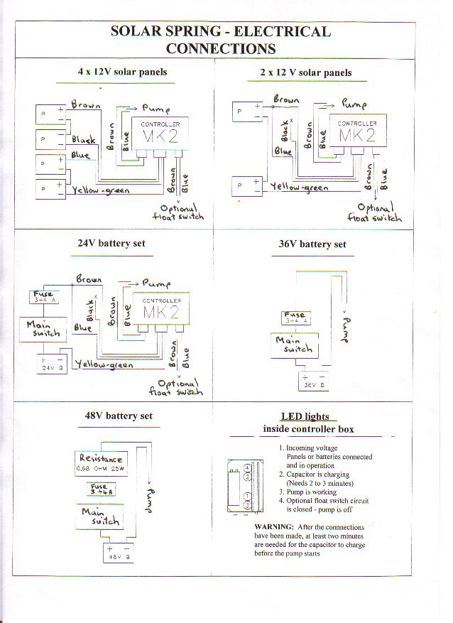
The
controller incorporates a self-diagnostic circuit which helps detect faults
during installation and maintenance. The LED lights can be seen when the back
of the controller box is removed by undoing the four controller box screws. The
LED lights are numbered in LOGICAL CIRCUIT ORDER, in order from the top 4,2,1,3
The LED
at the top (marked no. 4 on the diagram) lights up when solar voltage greater
than about 10V reaches the controller from the panels.
The
second LED (marked no. 2 on the diagram) lights up when the main capacitor is
charging. This phase lasts about two minutes.
The
third LED (no. 3 on the diagram) lights up when the controller sends output
voltage greater than about 10V to the pump motor.
The
fourth LED (no. 4 on the diagram) lights up when the pump motor stops because
the external (float) switch is in OFF mode.
For
more information on the LED lights refer to USE OF CONTROLLER DIAGNOSTICS
Despite the
presence of defence mechanisms built into the Sunprimer units, the
manufacturer's guarantee is voided where voltages higher than those prescribed
are used, even if such voltages are applied for a very short period of time.
Nor does the manufacturer's warranty cover the use of the Sunprimer with power
generators not being photovoltaic generators or, where Mk II units are used
with batteries, nor does it cover infiltration of water or external overheating
whether of solar or other origin. Consult your supplier BEFORE carrying out
laboratory testing, for which instructions will be given to interested parties.
THE
CONTROLLER ITSELF MAY BE DAMAGED IF VOLTAGES HIGHER THAN THOSE PRESCRIBED ARE
USED.
THE
PUMP MOTOR WILL BE DAMAGED IF CURRENT IS NOT CUT WHEN THE PUMP IS NOT WORKING.
The product guarantee for Solar Spring pumps and/or Sunprimer controllers
does not cover use with generators, even for a very short time, other than PV
panels and batteries, whether for testing purposes or otherwise. Nor does the
warranty extend to use of the products with voltages and/or currents greater
than those specified for normal conditions of use with 24V PV or battery
systems or with 48V PV panels systems using 4 panels each of 12V nominal
voltage as prescribed. Nor does the warranty cover loss or damage directly or
indirectly caused by lightning, water infiltration or externally caused
overheating whether of solar or other origin.
For
information on lightning protection please return to INSTALLATION INDEX
AVOID
leaving coils of surplus electric cable on-line at the well-head or elsewhere,
as these have been known to cause secondary inductive current and on rare
occasions confuse controller components.
It is
good practice to run the pump with an open head in a recipient for a few
minutes to make sure the valves are not stuck, BEFORE proceeding with the
installation of the pump. For a drawing, refer to:
DRAWING OF CONNECTIONS FOR THE SUNPRIMER MKII FIRST, TO
AVOID RISK OF SHOCK MAKE SURE YOUR ARRAY IS NOT IN OPEN CIRCUIT! Turn it away
from the sun, and/or cover it and/or disconnect one wire between two modules.
THEN
CONNECT THE SUNPRIMER TO THE MOTOR AS ALREADY DESCRIBED ABOVE.
CABLE
IDENTIFICATION SUNPRIMER TO PANELS DRAWING OF CONNECTIONS
FOR THE SUNPRIMER MKII The larger cable coming out of the bottom of the
Sunprimer unit is the inlet cable and it has to be connected to the
photovoltaic panels.
It has
FOUR WIRES, brown, black, blue, and green-yellow.
WHERE
YOU ARE USING FOUR STANDARD PANELS EACH WITH 36 CELLS WITH 12V NOMINAL VOLTAGE
AND A WORKING VOLTAGE FROM 14-17V AND AN OPEN CIRCUIT VOLTAGE FROM 18V-21V open
circuit voltages can reach 100V.
Panels
with 72 cells are now commercialy available. These are usually made by mounting
two standard panels each with its own electrical clips in the same frame. Extra
attention should in such case be paid to the electrical contacts because of the
risk of getting the electrical contacts of each of the two single panels mixed
up. Panels with a nominal voltage of 6V can of course also be used provided
they are grouped in lots of 24V as prescribed.
SOLAR
SPRING IS A 48V NOMINAL SYSTEM!
The
four photovoltaic panels are ideally divided into two pairs and the panels of
each pair are connected in series with 24V nominal voltage.
The
POSITIVE of the first pair of panels is connected to the BROWN wire of the Sunprimer.
The NEGATIVE of the first pair of panels is connected to the BLACK wire of the
Sunprimer.
The POSITIVE of the second pair of panels is connected to the BLUE wire of the
Sunprimer unit. The NEGATIVE of the second pair of panels is connected to the
YELLOW-GREEN wire of the Sunprimer.
If the
connections are incorrectly made, or if the two pairs of panels are different
from one another or exposed to the sun in a different way, the system MAY NOT
WORK at all or may not work properly.
If the
controllers are not new, it is good practice to check the positions of the
internal switches BEFORE proceeding with the installation.
The
Sunprimer will start the motor about two minutes after the circuit has been
completed.
WHERE
YOU ARE USING TWO PANELS with a Mk II controller: DRAWING
OF CONNECTIONS FOR THE SUNPRIMER MKII
Connect
the pump to the controller as for 48V installations. Then first connect
together the brown and blue wires of the largest cable coming out of the
controller, then connect the two panels in series so as to obtain 24V nominal,
then connect the positive of the pair of panels to the combined brown and blue
controller wires. Then connect negative of the panels to the yellow/green
controller wire.
Carefully
insulate the black controller wire, which is not used.
The
small float switch cable coming out of the controller is wired as for 48V
installations.
General
single- or two-pole on-off switches may if considered necessary be fitted on
the positive wires (or on the positive and negative wires) of the panels.
NEVER, NEVER insert any switch or other control device between the Sunprimer
and the pump.
Please
consult the manufacturer
With
the Mk II controller:
DRAWING OF CONNECTIONS FOR THE SUNPRIMER MKII
A
general single- or two-pole switch must be fitted to the positive (or to the
positive and the negative) of the battery set.
INSERT TWO
GOOD QUALITY 3 AMP FUSES (they are not supplied with the pump) in series on the
positive (combined brown and blue) wire between the battery set and the
controller. Standard motor vehcle fuses are appropriate.
Connect
the pump to the controller as for 48V installations.
Then first connect together the brown and blue wires of the largest cable
coming out of the controller, then connect the two panels in series so as to
obtain 24V nominal, then connect the positive of the pair of the battery set to
the combined brown and blue controller wires. Then connect negative of the
battery set to the yellow/green controller wire.
Carefully insulate the black controller wire, which is not used.
The small float switch cable coming out of the controller is wired as for
48V isntallations.
The product warranty does not cover damage caused by failure to install an
on-off switch or a fuse or by the failure of such switch and fuse to work
properly. For extra safety it is recommended that two identical fuses be
mounted in series.
To ensure optimum battery duration a good quality automatic system for the
control of battery charging and discharging cycles including LVD (Low Voltage
Disconnect) should be installed, in particular to avoid excessive or long
duration battery discharge conditions. The pump should work only when the
battery set is appropriately charged and should be switched off when the set is
discharged. The Mk II controller incorporates a device which switches the pump
off should the input voltage go down to about 22V. This device should be
considered a second line of defence and does not substitute correct manual or
automatic management of battery use.
The
Solar Spring pump may be connected WITHOUT CONTROLLER to 36V nominal
battery sets in cases where special current surge for start up is not required.
Do not
use pumps with 3mm or 2.6mm cams for battery applications without controller.
This is because:
a) 3mm
pumps need 56V on start up.
b)
Commercial fuses are inaccurate and may take some time to react
TWO
GOOD QUALITY 3 AMP SAFETY FUSES (they are not supplied with the pump) MUST BE
FITTED in series on the positive (combined brown and blue) wire between the
battery set and the controller. Standard motor vehcle fuses are appropriate.
The
product warranty does not cover damage caused by failure to install an on-off
switch or a fuse or by the failure of such switch and fuse to work properly.
Electric
connection on start up MUST ALWAYS BE INSTANTANEOUS. If the connection is
gradual and progressive, the pump may not start, and in this case high short
circuit current conditions would occur with the pump stopped, and this would
burn out the fuse.
ALWAYS
test with general switch and safety fuse fitted.
Refer
to comments under 24V battery systems concnering measures supporting optimum
battery duration.
Do not
use pumps with 3mm or 2.6mm cams for battery applications.
This is
because:
a) 3mm
pumps need 56V on start up.
b)
Commercial fuses are inaccurate and may take some time to react
48V
battery installations are potentially dangerous in that excessive surge current
can be generated unless appropriate steps are taken to avoid risk of
demagnetisation of the motor and rapid wear and tear of the motor brushes.
In addition to the general switch and the fuses mentioned for 36V battery
installations, 48V battery systems must also have both in actual installations
and during eventual tests an electrical resistance OF AT LEAST 0.68 Ohm to act
as a limiter. This can be installed by inserting between THE BATTERY AND THE
PUMP a 0.68 Ohm 25W resistor. The resistance of the electrical cable itself is
sufficient for this purpose provided AT LEAST 50 meters of 2.5mm2 cable or AT
LEAST 80 meters of 4.0mm2 cable or AT LEAST 120 meters of 6mm2 cable is
installed.
Installation of systems with battery sets over 48V nominal voltage is
PROHIBITED.
Although the system will work more effciently with 4 panels,three panels
can also be used.
The panels have to be connected in series as for two panels.
The configuration uses the full power of all three panels, but (just as is
the case for use with 2 panels) it does not use the series/parallel switching
mechanism. The system used will
therefore operate for fewer hours per day, and the system will operate slightly
less efficiently than it would with 4 panels. The starting power is the same as
it would be if there were just two panels, but the normal working power is that
of three panels.
Conditions of use lie between those for two panels and for four panels. In
typical conditions you would use 3mm cam with 4 panels (with the Hyboost) and
2.2mm cam with 2 panels (without the Hyboost). So, you would use in this case a
pump with a 2.6mm cam without the Hyboost unit with panels > 70Wp. If the
panels were smaller it would be better to use a smaller cam. If you try to use
a 3mm cam with Hyboost with 3 panels, you will not harm the pump, but the
system is going to start later in the morning, finish earlier in the evening,
and it may stop completely when clouds go over. It will therefore pump more
water when insolation is good but less water over the whole day. It would
therefore globally speaking operate less efficiently.
If certain types of high-voltage modules now being introduced to the market
are used with the Sunprimer in very cold areas, there is a risk that AT CELL
TEMPERATURES below -5 degrees C. it be advisable to install a voltage limiter
between the panels and the Sunprimer unit.
Generalmente,
se recomienda de 3 a 10 dmas de almacenaje. Esto depende del clima y su patrón
de uso. Para uso doméstico en climas nublados, 10 días es lo mínimo. En un
clima soleado, esto da un generoso margen de seguridad. Para irrigación
profunda de árboles (donde la tierra permanece húmeda por una semana) 3 días
pueden ser adecuados, porque la tierra misma provee almacenaje. Para irrigar un
jardín, 5 dmas pueden ser lo adecuado. !No puede almacenar demasiada agua!
Coloque
su punto normal de descarga mas alto que el fondo de su tanque de
almacenamiento, manteniendo así una reserva y así el tanque no se quede
completamente seco. Su tanque puede y se secará bajo cualquiera de estas
condiciones: un período de poco sol y/o alta demanda de agua, cualquier fuga
del ducto, cualquier falla eléctrica, falla de la bomba, descarga accidental
del tanque. Coloque una segunda valvula de salida en el nivel inferior de su
tanque de almacenamiento, pudiendo así descargar la reserva, en caso de
emergencia. Vea la ilustración.
Recomendamos
el uso de un switch de flotador para evitar un derrame de su tanque. Este accesorio
detendrá la bomba cuando el tanque se llene, y luego la reiniciará cuando el
nivel baje. Esto conserva el nivel del agua, previene derrames y elimina
trabajo de bombeo innecesario. Nuestro controlador permite el uso de un cable
pequeño a un switch remoto de flotador.
Advertencia:
El switch de flotador debe tener una acción opuesta. En otras palabras, tiene
que HACER contacto al subir, de tal manera que APAGUE la bomba. Su distribuidor
Solar Spring puede proveer este
accesorio.
Para
reducir el estancamiento (o prevenir congelamiento) con un mínimo desperdicio
de agua, instale una válvula justo abajo del nivel de desactivación del switch
de flotador, y ajústela para permitir una fuga lenta.
Es
práctica común limpiar o depurar un pozo y el suministro de agua despúes que
una instalación o servicio ha sido realizado. Esto se hace usualmente con una
solución de cloro o una preparación de cloro seca, vertida sobre el pozo. La
bomba distribuirá entonces la solución a través del agua del sistema. Pregunte
a su distribuidor local o autoridad de cuidado del ambiente un procedimiento
recomendado.
Solar
Spring NO será dañada por un tratamiento con dosis normales de cloro.
Index instalación bombas Solar Spring.
Some recommended technologies.
List of attachments to the Model.
Typical list of graphs and
drawings.
List of abbreviations used.
List of key words.
Documents for funding
applications.