Director,
T.E.(Terry)
Manning,
Schoener 50,
1771 ED
Wieringerwerf,
The
Tel:
0031-227-604128
Homepage:
http://www.flowman.nl
E-mail:
(nameatendofline)@xs4all.nl : bakensverzet
Incorporating
innovative social, financial, economic, local administrative and productive
structures, numerous renewable energy applications, with an important role for
women in poverty alleviation in rural and poor urban environments.
"Money is not
the key that opens the gates of the market but the bolt that bars them"
Gesell, Silvio The
Natural Economic Order
Revised English
edition, Peter Owen, London 1958, page 228
Edition 9:
Note : Your Solar Spring pump usually needs to be opened only :
1)
Where (after many years of use) parts subject to wear and tear may call for
replacement during the course of a systematic preventive maintenance visit.In
practice, intervention is limited to a long-term, periodic changing of the
motor brushes part 344, and to the cleaning of the bleeder nipple part 308
WIGGLE THE WIGGLE WIRE OF THE BLEEDER PART 308 WHENEVER FOR ANY REASON THE PUMP
IS WITH-DRAWN FROM THE BOREHOLE. Blockage of the bleeder is rarely critical for
pump operation. In the unlikely case you should ever find the bleeder blocked
please report this to your dealer.
2) Where, during installation, it is decided for purposes of optimisation to
change cam size.
3) The pump series number is marked on a ring under below the ovoid chamber,
under the rope hook.
YOUR SOLAR SPRING PUMP IS USUALLY SEALED FOR YOUR PROTECTION. We
strongly recommend that only authorised maintenance operators maintain your
pump. Breakage of the pump seal by unauthorised operators is considered to be a
serious breach of trust and will normally lead to suspension of all conditions
and benefits under the guarantee coverage. In presence of binding legislation
contrary to the contents of this clause 1 of this section, the minimum
legislative conditions shall prevail.
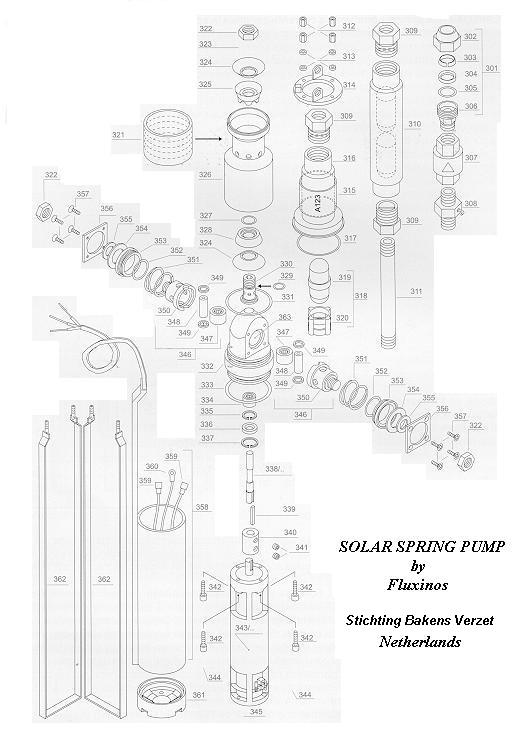
Unless otherwise expressly indicated, refer to drawing
to locate the parts numbers referred to.
Tools required : Spanner 8 MA; (optional) pump body clamp
(907);(optional ) a vice
Remove the self-locking nuts (312) then the tie-rod U strap washers
(313) from the flange (314) of the ovoid chamber .
Note : It is not usually necessary to remove the safety rope from bracket on
the flange (314) or to touch the rapid coupling (301) or the feed pipe at the
pump outlet.
Place the pump body clamp (907) if available in a vice (if available) to
stabilize the pump.
Ease the flange (314) off the threaded ends of the tie-rod "U"
straps (362) and slide the flange (314) along the electric cable to a point of
rest.
Note : It is not usually necessary to remove the ovoid (319) or the ovoid
centering piece (320) from the ovoid chamber (316)
Remove the filter (321).
The valve chamber (326) and the motor shroud (358) may be tight where
the "U-straps" (362) have been overtightened, slightly deforming them
or the filter (321).
For
access to the valve chamber (326) ease the valve chamber (326) off the pump
body group (363 etc) by freeing it from the upper body "O" ring
(331).
For
access to the motor, ease the motor shroud (358) off the pump body group (363
etc) with a screwdriver. The parts fit together tightly and it may be necessary
to clamp the pump body (322) around its widest part (the lower ring) and pull
firmly on the motor shroud (358) or vice versa.
YOU
NOW HAVE ACCESS TO THE MOTOR GROUP
Refer
to substitution of the motor brushes
WARNING!
There
is oil inside the pump body group. Refer to page 04.24 of this section for more
information. Do not remove the pump body group (363 etc) off the pump cam shaft
(338) or open the piston groups (347-357) without referring first to page
04.24.
Menu for the maintenance of Solar Spring pumps.
Some recommended technologies,
List of attachments to the Model.
Typical list of graphs and
drawings.
List of abbreviations used.
List of key words.
Documents for funding
applications.