Director,
T.E.(Terry)
Manning,
Schoener 50,
1771 ED
Wieringerwerf,
The
Tel:
0031-227-604128
Homepage:
http://www.flowman.nl
E-mail:
(nameatendofline)@xs4all.nl : bakensverzet
Incorporating
innovative social, financial, economic, local administrative and productive
structures, numerous renewable energy applications, with an important role for
women in poverty alleviation in rural and poor urban environments.
"Money is not
the key that opens the gates of the market but the bolt that bars them"
Gesell, Silvio The
Natural Economic Order
Revised English
edition, Peter Owen, London 1958, page 228
Edition 9:
The following pages contain the
basic information necessary for the installation of Solar Spring pumps. Those
interested in complete installation instructions should return to INSTALLATION INDEX, which can also be
consulted on any point in this summary you are not sure about.
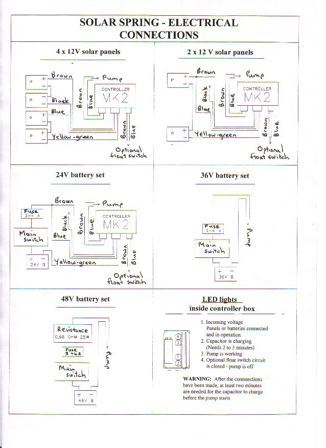
1.DRAWING OF CONNECTIONS FOR THE
SUNPRIMER MKII
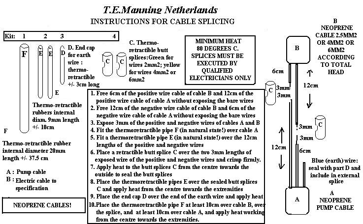
2. Connect the main submersible electric cable (of
the prescribed size and resistance) to the pump. See Which cable can be used by means of a
completely water-tight splice. For details of splicing kit and splicing
instructions see SPLICING INSTRUCTIONS
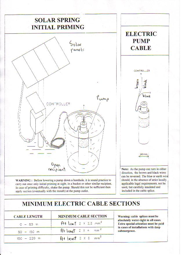
3. Fill an appropriate container with water and
immerge the pump in the water. See INITIAL PRIMING
4. Temporarily make all the electrical connections
by FIRST connecting the pump to the controller AND THEN the PV panels to the
controller.
5. Allow the pump to work in the container so as to
make sure first that it is primed and secondly that everything is in order. See
INITIAL PRIMING
6. Disconnect the electrical cables FIRST the cable
between the PV panels and the controller AND THEN the cable between the
controller and the pump, and remove the pump from the water in the container.
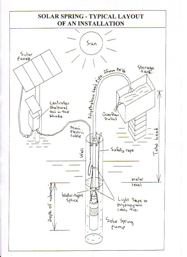
7. Have a look at: DRAWING OF
THE GENERAL SYSTEM LAYOUT.
8. Connect the prescribed polyethylene feed pipe to
the pump using correctly the rapid couplings supplied, and the safety rope. See
Measuring and cutting feed pipe for more
detail.
9. Lower the pump into the borehole holding it by
the polyethylene pipe and the safety rope. NEVER put any load on the electric
cable. See Placing pump for more detail.
10. Try to make sure the pump is below the minimum
foreseeable water level in the borehole, and at the same time not more than
5-10 meters below that minimum level. See Placing
pump for more detail.
11. Make sure the polyethylene feed pipe, which has
to carry the weight of the installation, is sercurely anchored at its upper
end.
12.Make sure the safety rope is at least a meter
longer than the polyethylene feed pipe.See Fitting
safety rope
13.Make sure the electric cable is at least one
meter longer than the safety rope.See Length
of electric cable
14.Install the controller in a vertical position in
a dry, ventilated, shady position. See Fitting
Sunprimer electronics on panel support
15.Install any on-off switches or fuses eventually
considered necessary (in a separately hermetically closed box) between the panels
(or the battery set) and the controller. NEVER place them between the
controller and the pump. In case of use with batteries, a general on-off switch
and a safety fuse must be used. In case of direct PV applications an on-off
switch is not considered essential, but many operators are accustomed to using
one.
16.Overflow pipes should be preferred to float
switches in tanks.
17.Water level probes down the borehole are not
necessary. Solar spring pumps can be submerged below the lowest foreseeable seasonal
water level in the borehole and in any case can run dry without damage.
18.Make the necessary electrical contacts connecting
FIRST the controller to the pump AND THEN the controller to the panels or to
the battery group.
19.In case of problems, open the controller box and
observe the behaviour of the four LED lights forming the self-diagnostic
circuit. See Use of controller diagnostics
Sunprimer controllers incorporate a
surge start mechanism with a large capacitor, various safety devices to protect
the system against overloading, and four small LED lights for self-diagnostic
purposes which can be seen when the lid of the controller box is removed. The
lights are numbered in logical circuit order from top to bottom 4,2,1,3.
All four LED lights remain off when no current
arrives from the PV array or battery set.
When the pump is not going and current starts to
arrive from the PV array or battery set, the controller keeps the pump stopped
and loads the capacitor, and the 1st (the third LED from the top) and 2nd LED
(the second LED from the top) lights are on.
When the capacitor is charged (this usually takes
about 3 minutes with the Mk I/d and Mk I/e controllers and 2 minutes with the
Mk II controller), the controller starts the pump, and the 1st (the third LED
from the top) and the 3rd LED (the bottom LED) lights are on.
If everything is normal, the pump continues to run
with the 1st (the third LED from the top) and the 3rd LED (the bottom LED)
lights on. If the pump turns too slowly or tends to stop (because there is less
than about 22V at the controller input due to inadequate insolation or low
battery charge), or if the load is too high (current is more than about 4.5 amps)
the controller will switch the pump off and the 3rd LED (the bottom LED) light
will go off.
When the pump has stopped, the cycle re-starts.
Delay in start-up of a Solar Spring pump after
installation and after electrical contacts have been made, or after every
attempt to re-start as above described, is therefore always about three minutes
(Mk I/d and Mk I/e controllers) and two minutes (Mk II controller), as this is
the time usually needed to charge the capacitor. Early in the morning the pump
will attempt to start many times only to switch itself off immediately, until
such time as enough current is available to run the pump.
When the circuit controlling the float switch or
other external device (the smallest controller cable) is CLOSED (i.e. when contact
is made) the controller swtiches the pump off and the 4th LED (the top LED)
lights up.
there is a fault in the electrical connections.
there is a fault in the electrical
connections.
but after three minutes (Mk I/d and
Mk I/e controllers) or two minutes (Mk II controller) the third LED (the bottom
LED) fails to go on, then there is either:
a) a fault in the electrical circuit or
b) insufficient insolation or
c) the battery set is undercharged.
but the pump stops immediately,
then there is either:
a) a fault in the electrical connections or
b) insufficient current available, or
c) the feed pipe is blocked or iced up, or
d) the pump has a cam which is too large for the installation in question, or
e) the PV array is too small for the application in question, or
f) the electrical cable is too small (resistance too high) or
g) the pump is oversubmerged.
and the pump works with a capacity
lower than what it should be according to the tables supplied, then there is
either:
a) a fault in the electrical connections, or
b) insufficient current available, or
c) the feed pipe is partly blocked or iced up, or
d) the pump has a cam which is too large for the installation in question, or
e) the PV array is too small for the application in question.
but the pump does not produce any
water, then there is either:
a) a fault in the electrical circuit, or
b) current to the pump is cut due to breakage of the electric cable or system
short cicuiting (motor brush wear after 5-7 years' use), or
c) the pump is running dry, or
d) the pump is not primed, or
e) the feed pipe is blocked or iced up.
Measure the current and the resistance of the pump circuit.
there can be either:
a) faults in the electrical connections, or
b) the operation of an eventual fuse (if the fuse burns frequently and there
are no short circuit phenomena increase fuse size by 1 ampere), or
c) safety devices have shut the controller down (eventually contemporaneously
with fuse burn out) because of wrong manoeuvres, or
d) atmospheric discharge, or
e) controller damage
Remove the block by separating and re-connecting the panels or the battery set
and substituting any burned out fuses. Should the controller get blocked again
immediately or systematically, then the safety devices have detected internal
controller damage.
Some recommended technologies.
List of attachments to the Model.
Typical list of graphs and
drawings.
List of abbreviations used.
List of key words.
Documents for funding applications.